
In the field of printed circuit board (PCB) design and manufacturing, especially high-power applications such as high-performance LED lighting systems for cars or motorbikes, switching power supplies, or power modules, etc., thermal management is always one of the biggest challenges. Direct Thermal Path (DTP) technology was born as an effective solution to significantly improve the heat dissipation capacity of PCB circuits compared to traditional technologies using conventional Aluminum/Copper core circuits (Metal Core PCB). Let’s learn about DTP technology and its applications with Hatakey Electronics through this article!
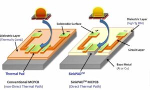
Figure 1. LED circuit processed on traditional metal core circuit and by DTP method
1. Traditional Metal Core PCB (MCPCB)
Metal Core PCB (MCPCB), also known as Insulated Metallic Substrate (IMS) PCB or Thermal PCB, is a familiar choice for us when designing boards with special heat dissipation requirements such as high-power LED systems… In contrast to the traditional glass core FR4 circuit, these are PCBs with a core made of metal material (usually aluminum or copper) used as a heat sink for important components on the board.
Users can choose their base core material based on different applications. Among all these metals, considering thermal conductivity, hardness and cost, aluminum is the most economical choice. Copper has better performance but is relatively more expensive.
MCPCB circuits usually consist of a conductive copper layer, an insulating layer and a metal substrate.
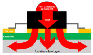
Figure 2. Basic structure of a traditional aluminum core circuit
2. What is Direct Thermal Path technology?
Direct Thermal Path (DTP) or Direct Heatsink is a PCB technology that allows heat to be transferred directly from the heat-generating components to the heatsink layer, without having to go through many layers of insulating materials as in conventional PCBs. The core of DTP lies in the design of metal heat conduction zones (usually copper) that run from the component mounting surface to the heatsink core layer, forming a “direct thermal path”.
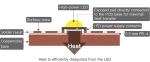
Figure 3. DTP Direct Thermal Transfer Technology
Structure of the DTP PCB circuit
Top Copper Layer: where components are mounted, especially power components such as MOSFET, LED, IGBT, etc.
Direct Thermal Conduction Layer (Thermal Pad or Metal Core): usually a thick copper plate or metal core located right under the heat-generating component.
Dielectric Layer: optimized for the lowest possible thermal resistance.
Metal Core: usually aluminum or copper, helps conduct heat to the heat sinks or case.
3. Outstanding advantages of Direct Thermal Path technology
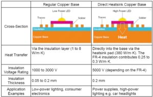
Figure 4. Comparison between traditional copper circuit technology and direct thermal path technology on copper core circuit
🔥 Outstanding heat dissipation capacity: For traditional copper-aluminum circuits, heat from the components must be transferred through a new insulating layer to the metal core layer below, so the heat transfer coefficient is usually only 1-8 (W/m.K). For DTP technology, the heat transfer coefficient can be up to 380 (W/m.K).
⚡ Suitable for high-power applications: such as high-power LEDs, automotive electronics, DC-DC sources, telecommunications equipment, etc.
🔧 Flexible design: DTP areas can be customized to suit each separate component or component cluster.
📏 Support for compact circuit design: due to high heat dissipation efficiency, there is no need for bulky peripheral cooling solutions such as separate heat sinks or fans, etc.
4. Application of Direct Thermal Path technology
- Industrial LED lights and outdoor lighting, super bright LEDs on cars, motorbikes…
- High power honeycomb power sourceHigh efficiency LED driver
- Electric motor control circuit
- Renewable energy converter (solar inverter, wind controller…)
5. Notes when designing and manufacturing DTP PCB

Figure 5. Notes on Direct Thermal Path Design
When designing Direct Thermal Path circuits, the direct thermal contact between the component and the copper core should be drawn as a square or polygon with a minimum width of 1mm in all directions. Note that this heatsink should not be connected to the surrounding copper parts or circuit lines unless you want to extend the heatsink.
The heatsink should be shown on a separate layer and clearly annotated. This helps the factory easily grasp the location and size of the heatsink holes, and understand the design intention.
Via holes cannot be used because the holes on the FR-4 layer are not plated. The minimum drill diameter is 1mm; the minimum slot width is 1.6mm. The circuit will usually be plated with OSP after completion. Copper core circuits can often be plate-mounted for ease of soldering but will only accept V-groove milling. You should consult and carefully check the factory’s machining capabilities before ordering the circuit.
Controlling the dielectric layer is extremely important – it must be thin with good heat transfer ability but still ensure good insulation.
Mechanical processing such as punching holes, punching cores requires high precision, avoiding affecting heat transfer performance.
Ensure uniformity between DTP areas to avoid hotspots on the PCB surface.
Consider cost and efficiency – DTP technology is often more expensive than traditional PCBs, but is a worthwhile investment for applications requiring high heat transfer performance.
6. Conclusion
Direct Thermal Path technology is an important step forward in solving the problem of heat dissipation on modern PCBs. With the ability to transfer heat directly and quickly from components to the heat sink, DTP not only helps improve working efficiency but also increases the durability of the entire electronic system.


 Tiếng Việt