
Thermal management plays an important role in ensuring the reliability and performance of high-power electronic devices. Excessively high temperatures can have adverse effects on electronic components, leading to reduced performance, shortened lifespan, and increased failure rates. In this article, let’s explore with Hatakey Electronics the core points of thermal management that we need to pay attention to when designing high-power boards and learn about the methods and techniques commonly used to manage heat in electronic systems.
1. Effects of temperature on electronic components
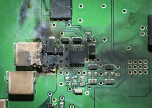
Temperature is considered the mortal enemy of electronic components. They often affect:
Semiconductors: High temperatures can cause instability in the response of semiconductors. This leads to unstable performance and other potential risks.
Material Fatigue: Constant temperature fluctuations can cause material fatigue, accelerating the wear and tear of components over time. Electron Migration: Extreme temperatures (extremely high and low) can lead to electron migration, a phenomenon in which atoms in metals in general and printed circuit boards in particular are displaced due to thermal stress, potentially compromising the integrity of the circuit.
2. Thermal Management Challenges in Power Circuit Design
High-power electronic devices typically generate large amounts of heat, sometimes exceeding 100 W/cm2. As the power of the device increases, heat dissipation becomes more difficult. Several factors contribute to the thermal management challenges in high-power applications:
Low thermal conductivity: Many materials used in electronic components, such as circuit boards and printed circuit boards, have relatively low thermal conductivity. This hinders the efficient transfer of heat away from critical components, creating bottlenecks in the heat transfer paths.
Power density: High power density leads to localized hot spots, where heat is concentrated in a small area. These hot spots can lead to thermal runaway, reducing the performance and reliability of the electronic system.
Thermal Stress: Components in electronic systems often have different coefficients of thermal expansion (CTE). As temperatures change, these different CTEs can cause thermal stress, potentially leading to mechanical failure or solder fracture.
3. Thermal Management Strategies for Safe Circuit Operation
Operating electronic components within a safe temperature range is essential to maintain optimal performance and extend their lifetime. To achieve this, several techniques can be used in thermal management:
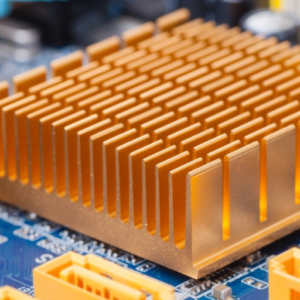
Heat sinks and heat spreaders:
Heat sinks and heat spreaders are commonly used to dissipate heat from high-power components. These components are designed to increase the surface area available for heat transfer, allowing for more efficient cooling. A heat spreader is a flat metal plate that provides a smooth, flat, large area for mounting to a heat sink (such as the outer metal plate of a computer CPU).
Thermal Interface Materials (TIM)
Thermal interface materials, such as thermal tape or thermal paste, are used to improve the thermal conductivity between the surface of the component and the heatsink. These materials fill the microscopic air gaps, enhancing the heat transfer efficiency.
Liquid Cooling
Liquid cooling systems, such as cold plates (with coolant running inside), microchannel heat exchangers, provide superior heat dissipation compared to conventional air cooling. By circulating the coolant through channels or tubes, large amounts of heat can be efficiently removed from high-power components.
Active Cooling
Active cooling techniques, such as the use of fans or blowers, increase the air circulation around electronic components. This increases the heat transfer to the surrounding air.
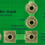
Thermal Vias
The thermal vias are thermal paths on the PCB that conduct heat from high-power components to the outer layers of the PCB. Additionally, using PCBs with thermal cores or in combination with thick copper layers can enhance thermal conductivity and heat distribution.
Component Layout
The logical placement of high-power components on the PCB can help avoid thermal coupling between heat sources. This prevents localized hot spots and promotes even heat distribution throughout the system.
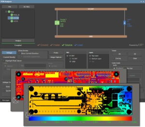
Thermal Simulation
Computational fluid dynamics (CFD) and finite element analysis (FEA) tools are used to simulate temperature distribution, identify potential hot spots, and optimize the thermal design of the PCB. These simulations help predict and mitigate thermal issues before manufacturing.
4. The Role of Software in Thermal Management
Modern electronics often use software-controlled thermal management techniques to optimize heat dissipation and energy efficiency:
Dynamic Frequency Scaling: Adjusts processor speed based on workload.
Fan Curves: Optimizes cooling efficiency. Fans operate at higher speeds as temperatures increase and vice versa, ensuring adequate air circulation and heat dissipation.
Thermal Throttling: In critical situations, electronics can use thermal throttling, where the system reduces performance to manage excessive heat dissipation. This protects components from the risk of thermal damage.
5. New trends and approaches in thermal management:
Nanomaterials: Lightweight materials with high thermal conductivity, such as graphene, carbon nanotubes, and nanodiamonds, can help improve heat transfer and heat dissipation.
Immersion Cooling: Integrating coolant channels within the chip for optimized cooling.
AI-driven management: Artificial intelligence (AI) algorithms are being developed to monitor and respond to thermal conditions in real time. These algorithms optimize system performance and energy efficiency by adjusting cooling mechanisms based on temperature data.
6. Thermal Management Testing and Evaluation:
Thorough testing and evaluation are essential to ensure thermal management performance and reliability of high-power electronic systems. Some common methods used for testing and evaluation include:
Thermocouples: Temperature measurement using thermocouples attached to the surface of component housings and printed circuit boards provides real-time data on component temperature.
Infrared thermal imaging: Powered assemblies can be analyzed using infrared thermal imaging to map surface temperatures and identify hot spots. This non-contact approach enables rapid and comprehensive thermal analysis.
Thermal mechanical simulation: Simulation tools can model heat flow, airflow, and structural stresses to predict reliability risks and optimize designs.
Thermal cycling testing: Components are subjected to temperature cycling between extreme temperatures to simulate thermal-mechanical fatigue failures. This process can provide data on the thermal endurance limits of the component.
Destructive testing: Destructive testing exposes components to high temperatures for extended periods of time to detect early-stage failures.
7. Conclusion:
Effective thermal management is essential in high-power electronics to ensure optimal performance, reliability, and lifetime of electronic components. Densely packed device footprints with high densities of I/O pins enable the creation of complex ICs but pose thermal design challenges. By applying thermal vias, heatsinks, TIMs, and advanced cooling techniques, you can effectively control temperatures and ensure high system performance.
Thermal design modeling, testing, and validation are essential at every stage of an application. As the demand for high-performance electronic systems continues to increase, the field of thermal management continues to grow. We hope that this article has provided you with useful knowledge to help you implement effective thermal design and management strategies in your electronic projects!


 Tiếng Việt